Software Defined Radio Network Testbed
Because concurrent cooperative transmission
(CCT) is not supported by any current standard, we have constructed
an ad hoc network of 20 software defined radio (SDR) nodes on which
to develop CCT PHY, MAC and network layer protocols.
Fig. 1 shows a SARL SDR node, which
is composed of a GNU radio and a MICAZz mote. The GNU radio includes
a USRP1, a 2.4 GHz band RF Daughterboard, and a PC.
The Daughterboard is the RF front end, which performs RF-IF
conversion. The USRP1 has an
ADC/DAC and an FPGA. The FPGA converts the IF signal to baseband and
performs certain other minor radio functions. The baseband samples
are transmitted over a USB connection to and from the PC, where the
baseband signal processing is performed. The MICAz is used only for
telemetry and experiment setup, that is, it reports information
about the SDR, wirelessly, in a different part of the ISM band, so
that its signals do not interfere with the GNU radio’s signals. The
MICAz is used to set the GNU radio parameters, such as its frequency
of operation and, in some experiments, what diversity channel it
should use. The
telemetry network (TeNt) is described in more detail below.
|
Custom expansion connector for the |
|
MICAz radio (attached up-side down) |
|
Daughter (RF) board |
|
USRP1 |
|
Figure 1. On the left, components |
|
PC |
|
USB connection |
|
GNU radio |
|
TENT node (MICAz) |
|
SDR node symbol |

Figure 1:
On the left, components of the SARL SDR node; on the
right, the SDR
|
Figure 2. A cart containing two SDR |
 One
One
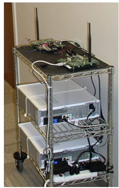
or more SDR Nodes can be placed on rolling carts, as shown in Fig.
2, for ease of setting up desired network topologies.
Fig. 3 (a) shows an example multi-hop topology, where some
carts have four nodes (to test cooperative transmission from a small
cluster), and some carts have only one node, to enable comparison
between CT-based and non-CT-based (i.e. conventional) routing
protocols. Fig. 3 (b) shows
the carts placed for an experiment.
The software Python and C++ is used to code the
SDR modules.
Figure
2. A cart containing two SDR nodes.
|
Figure 3. |
|
(a) |
|
(b) |

Figure 3.
(a) An example multi-hop network topology for short-range
experiments. (b)
The carts placed in a short-range multi-hop topology.
Telemetry Network (TeNt)
|
Figure 4. The connections between |
|
|
|
USB |
|
GNU |
|
USRP1 |
|
MICAz |
 The
The
purpose of the TeNt is to wirelessly control the GNU radio
parameters and observe the operations of all the GNU radios in the
network without interfering with them. The TeNt is a MICAz network
and a graphical user interface (GUI).
The TeNt enables quick topology changes in the GNU radio
network, and a convenient way to set up experiments. As shown in
Fig. 4, the MICAz has separate wired USB connections to both the PC
and the USRP1, to monitor GNU computations that are being done on
both platforms without interfering with the GNU radio USB connection
between the USRP1 and the PC. A custom expansion connector was
created to provide the MICAz-USRP1 connection; the connector also
replaces the Programming Board (MIB510) and provides power to the
MICAz. Examples of telemetry information include the packet error
rate (PER), RSSI, and the number of packets transmitted.
Examples of control parameters include frequency, transmit
power, and receiver gain.
The TeNt has a multi-hop architecture with a
single Base Station (BS). The BS is a MICAz node that is connected
to a PC. Since the
range of cooperative transmission of the GNU radios is longer than
the range of the MICAz’s, additional MICAz nodes that are not
connected by wire to a GNU radio are distributed between GNU radios
to provide connectivity in the MICAz network.
An example of the graphical user interface
(GUI) is shown in Figure 5. The GUI user drags and drops the nodes
to their approximate locations in the network.
The node colors indicate which nodes participated in a
concurrent cooperative transmission (CCT).
Fig. 6 shows how the relative firing or
transmission times in CCT are measured for small cluster sizes. One
USRP1 board (the one in the center) is not used as a GNU radio node,
but instead monitors four I/O pins; one pin is on each of the USRP1
boards of the GNU radios in the cluster.
The I/O pin changes state
when the GNU radio transmits.
|
Figure 5. A screen on the GUI, |

Figure
5
A screen on the GUI, showing node locations.
SHAPE
* MERGEFORMAT
|
Figure 6. The node in the middle is |

Figure 6. The node in the
middle is being used only to monitor the firing times of the four
other nodes
Figure 7 shows nine GNU radios on a cart that
is used for range extension measurements.
Each GNU radio on the cart receives the signals coming from a
relay cluster, and records a packet error rate (PER).
Because the receivers are sufficiently separated in space,
each PER corresponds to an independent multi-path fading
realization.
SHAPE
* MERGEFORMAT
|
Figure 7. Nine SDRs on the |

SHAPE
* MERGEFORMAT
|
Figure 8. |

Figure 7. Nine SDRs on the “receive” cart for range
extension measurements.
Figure 8.
The code blocks for the PHY and NET parts of the
communications stack. No
MAC is needed for the OLAROAD protocols, since there is no
contention.
|
Figure 9. |
The
Creaters
We are indebted to the three students who spent
one year building our SDR network testbed.
Steve James William, who did the networking programming, Yong
Jun Chang, who did the physical layer programming, and Vivek Agate,
who created the TeNt.


